


Mounting Procedure

Holemaking Accessories – Enhancing Precision and Efficiency in Drilling Operations
In modern manufacturing, precision and process efficiency are essential to maintaining competitiveness and meeting high quality standards. Within drilling operations, Palbit’s holemaking accessories are engineered to optimize tool performance, reduce setup times, and provide greater flexibility in machining strategies.
These specialized accessories contribute to more reliable and streamlined production by improving dimensional control and minimizing downtime caused by frequent tool changes or manual adjustments.
CHAMFERING RINGS
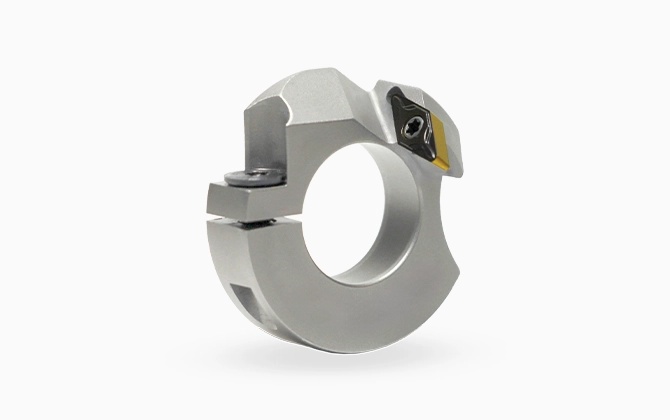
CHAMFERING RINGS
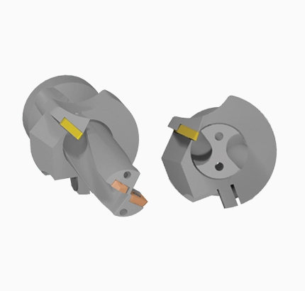
Designed for streamlined workflows, these chamfering rings facilitate the simultaneous drilling and chamfering of workpieces. This dual-operation capability minimizes cycle times and lowers the tooling inventory required for hole preparation, contributing to improved efficiency and reduced machine downtime associated with tool changes.
Features:
- Integrated on Drill: simultaneous hole drilling and chamfering in one operation
- VBMT insert: the chipbreaker and grade should be specifically engineered to match the insert being used within the chamfering ring to ensure suitable workpiece machining
- Versatility: compatible across all range of jet drills program
Mounting Procedure for Chamfering Rings
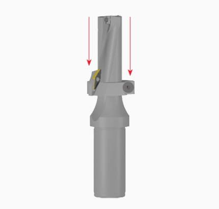
PROCEDURE 1
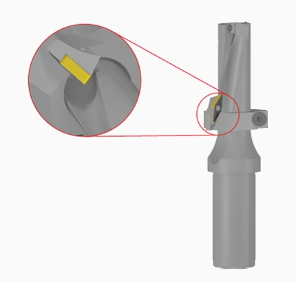
PROCEDURE 2
PROCEDURE 3
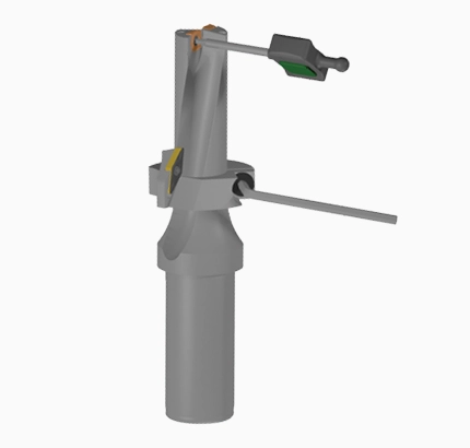
PROCEDURE 4
ECCENTRIC SLEEVES
ECCENTRIC SLEEVES
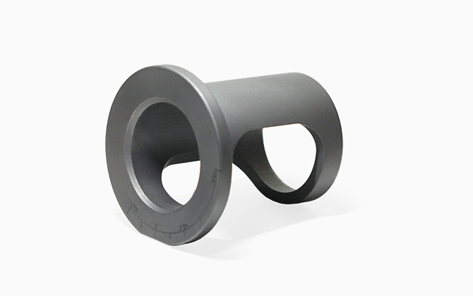
Palbit eccentric sleeves: a user-f riendly system that provides a versatile and effective solution accurate hole decentring and adjustable positioning. Their ingenious off-centre bore design allows precise micro-adjustment of drill positions, easily adapting to different requirements and tolerances. This cost-effective approach reduces the need for numerous f ixed-size parts by allowing adjustments for different effective diameters and minor misalignments , during drilling processes.
Features:
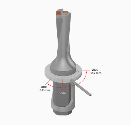
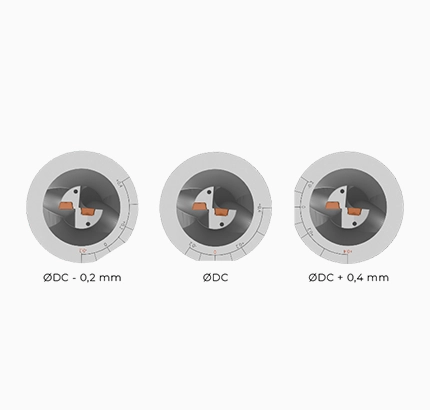
- Fine diameter adjustment: slight drill axis shift for precise sizing
- Adjustable hole decentering: enables fine-tuning of the bore’s offset from the intended center
- MaxPro Drill: eccentric sleeve integration for offset capabilities
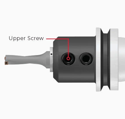
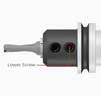
Mounting Procedure for Eccentric Sleeves
PROCEDURE 1
PROCEDURE 2
PROCEDURE 3
PROCEDURE 4
NOTES:
-
Reduce the feed rate by approximately 20% for 2D and 3D drills, and by 30% for 4D and 5D drills.
-
Designed for use with DIN 1835.
-
Not for use with lathe tools.